Electroacoustic Multiplexing Telegraph – US Patent 185507
Here is one of the early patents for electroacoustic multiplexing of telegraph signals. (Note that this is not the same as electroharmonic multiplexing, which used multiple frequencies as carrier waves to achieve multiplexing.) I like this one because it really shows the acoustic component of the system. Here is a picture of a quadruplex system.
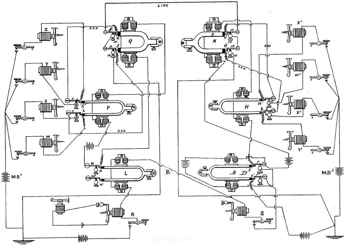
Now, if you try to run through the circuit diagram and work it out for yourself, you might run into some problems. The diagram differs slightly from the description in the body of the patent. Since a number of different inventors were scrambling to lay claim to the idea of acoustic multiplexing, I would guess that this is a result of rushing the patent down to the patent office. Anyway, I’ll run through the circuit and describe the basics.
First, we have two stations, one on the left and one on the right. Furthermore, there are two lines between the stations. The bottom line marked B carries a control signal, and the main line marked LINE carries the multiplexed communication signal. The two tuning forks at the bottom marked L (on left side) and A (on right side) are part of the control circuit, which could also be described as the master timing circuit.
Now, let’s focus on the “master clock” of the system. This is the tuning fork at the bottom of the right side station, and is shown magnified below.
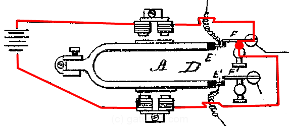
The red line shows what was quite a revolution at the time (and just to be clear, this patent was not the one that invented it). It is an electromechanical clock device, the forerunner to the crystal oscillators used in modern electronics. At this point, it is important to note the vibration mode of a tuning fork is such that the forks alternately move away from each other and then move towards each other. When the tuning fork is at rest, the circuit is closed and the magnets are energized. This pulls the forks away from each other. The tip of the upper fork E then pushes outwards on F, breaking the connection at F. This cuts the circuit and de-energizes the magnets. The forks are now freed to oscillate back inwards at the resonant frequency of the fork. This again closes the switch, activates the magnets, and the oscillation continues sustained by the battery.
This master clock generates two clock signals which are sent to different parts of the circuit. They are kept electrically isolated by being connected to separate switches at the ends of the two different forks. The clock signal from the lower fork is sent out over the control line as the synchronization signal to the remote station, whereas the clock signal from the upper fork connects to the multiplexing apparatus above. Now, in this next figure I’ve highlighted the control signal circuit.
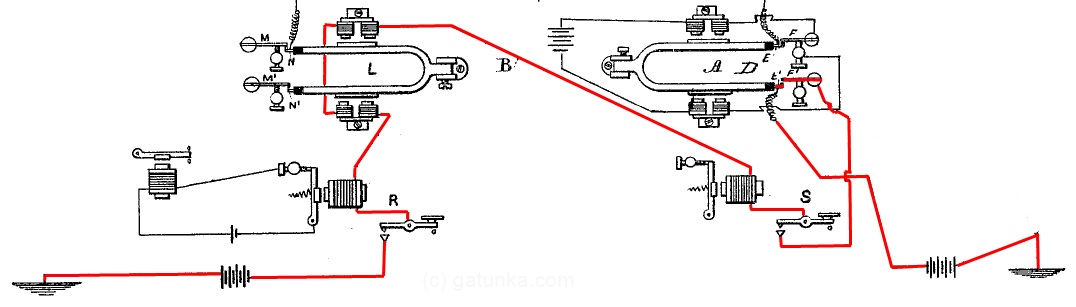
There are two points to note. The first is the extraneous battery at the bottom left. This battery would either need to be removed or reversed for the system to actually work. The second point is that the schematics marked R and S in the figure represent telegraphic keys that have a normally closed configuration. That is, the connection through the keys is closed when the keys are not pressed, and gets broken by pressing the keys. These keys are not considered part of the multiplexing arrangement, but form an out-of-band communication channel. The short breaks in the synchronization signal from sending Morse code down the same line has no effect on the synchronization because the tuning forks are able to remain in sync for 20 to 30 seconds even after the synchronization signal has been removed.
Starting from the right, we can see that the line from the battery passes across the E’ and F’ contacts at the lower fork of the master clock, through the normally closed telegraph key S and then across the control line B to the remote station. The line then passes through the electromagnets on the tuning fork L, causing the tuning fork to vibrate in sympathy and synchronously with the master clock A. This is the key to the timing system, and creates a slave clock at the remote system that is synchronized with the master clock. The line then runs through more telegraphic equipment and back to earth (once we remove the extraneous battery).
The tuning fork L is connected similarly to A, with the upper fork used as the timing signal for the multiplexing circuit at the remote station. The bottom fork of L (with the contacts marker M’ and N’ is not used in the diagram, but could be used in repeater stations to daisy chain the signal on to a subsequent telegraph line segment.
Next, we’ll look at the multiplexer.
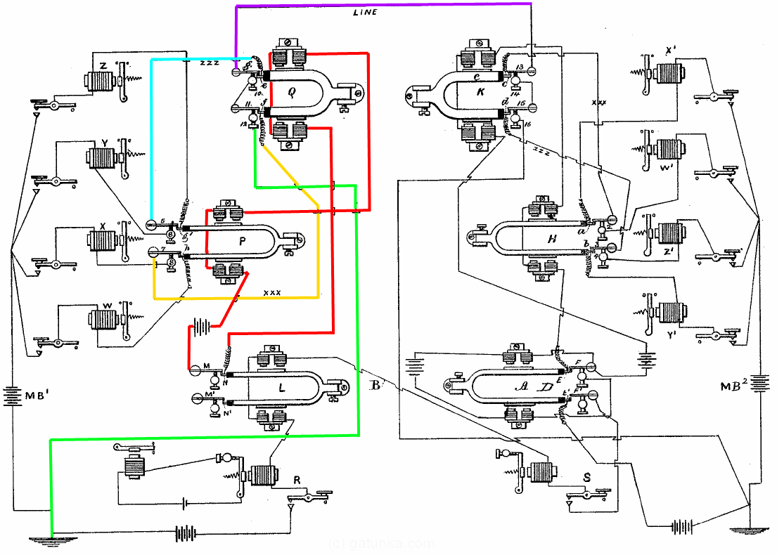
The first thing to note is that the left and right side multiplexing circuits are symmetrical (despite how the schematic may appear), so I’ll only detail one side. The red line shows the circuit from the timing master, which runs through the P and Q tuning fork clock drive magnets. Notice how the P fork looks similar to the L timing master while the Q fork is shorter and fatter? This is because the P fork has the same resonant frequency as the timing master, while the Q fork has a resonant frequency double that of the timing master. This is because the Q fork divides the main line into 2 virtual circuits, and the P fork subsequently divides these 2 virtual circuits into 4 virtual circuits.
The forks of the Q tuning fork can be thought of as having 3 states. In the rest state or central state when the forks are not flexing inwards or outwards, the green line is connected through to the purple main telegraph line, and the orange and cyan lines are disconnected. When the forks are flexing outwards, the top fork switch is engaged and the main line gets connected to the cyan line, and when the forks are flexing inwards, the bottom fork switch is engaged and the orange line gets connected to the main line.
The same configuration on the right hand side means that we get 4 complete virtual circuits operating over the same line. This basically completes the apparatus, and we have a quadruplex communication system.
Although it turns out that adjusting the placement of all those switches at the ends of the tuning forks and getting all of the magnets wound and placed symmetrically so that everything works as intended is problematic, it is not insurmountable. The real issue is continuity. Each virtual circuit is only connected (at most) 1/4 of the time, and the output is disconnected for the rest of the time. To achieve this we really need a more machine-friendly signaling system.
Related Posts
Tweet