Synchronous Distributor Multiplexing – US Patent 143341
This is an early attempt at an isochronous distributor-based multiplexing telegraph from 1873. It demonstrates the problematic nature of using Morse code with this kind of multiplexing system. First, let’s have a look at the top view of the device.
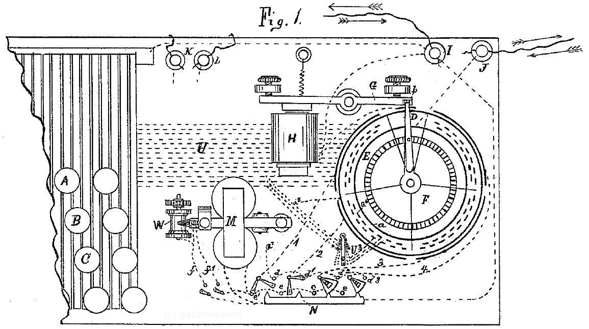
It looks like a bit of a mess. So here’s a color-coded version for describing the operation.

The most important part is the distributor on the right, which is colored orange. The red needle carries the signal to and from the telegraph wire, and rotates clockwise around the dial. Notice how the dial is divided into 4 large segments and 1 small segment. The 4 large segments correspond to 4 multiplexed circuits (called virtual circuits), and the small segment is a synchronization segment. Just outside of the orange circle, you can see lines corresponding to each of the segments. These are contacts that are used for receiving. Within the orange area there are 15 contacts in each virtual circuit, and these are used for transmitting.
First, let’s look at how the synchronization worked. The pink circle is a toothed gear that is driven clockwise by a motor underneath (not shown in the diagram). The red needle has a pin sticking out from its bottom which engages with this gear, and drives the red needle around. However, the red needle can also be lifted up out of the gear so that it comes to a halt. In the state shown here, the red needle is sitting on top of the green arm, which disconnects it from the drive motor. This is the idle state.
In this state, the telegraph signal from J goes into the red needle, then into the contact between the green arm and orange circle, through to the green electromagnet marked H, and then back out to the telegraph signal at I. When a synchronization signal is received from the telegraph line, it activates the electromagnet, which pulls back the green arm, and drops the red needle onto the spinning pink gear. The red needle can then perform one full rotation until it beaches itself on the green arm once again. Anyone who knows RS-232C should be able to see the similarities. (For those who don’t know, RS-232C was the predominant serial communication protocol on computers until it was replaced by USB. It consisted of a start bit, followed by 8 to 10 bits clocked based on the timing when the start bit was received. This meant that a separate clock signal was not needed.) The synchronization signal here corresponds to the start bit in RS-232C.
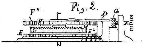
Here is a side-on view of the distributor, which might or might not make things clearer.
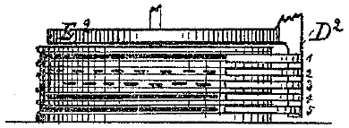
Since it is a patent, it also has an alternate design for the distributor which accomplishes the same thing.
Now, because of the style of synchronization used, the motors can have some slight difference in rotation speed without breaking the multiplexing function. In this case, a speed difference of a few percent would not be a problem. However, it’s not at all clear from the patent if the inventor was actually able to achieve even this degree of consistency from his motors. There is a motor design included in the patent, which I’ll get into later.
Getting back to the multiplexer, let’s take a look at the method of transmission. The basic premise is that one letter is sent with each transmission window (i.e. with each revolution of the distributor). Since Morse code consists of dots and dashes, a system of producing transitions at the correct timings was needed. In the orange part of the distributor ring, there were 15 sequential contacts, which are sent in turn as the distributor rotates. Setting up the correct sequence on the contacts can allow us to send Morse code. The 15 contacts were thus connected to 15 lines that ran underneath the keyboard, with each key press connecting the wires as appropriate to transmit the correct letter. This can be seen below:
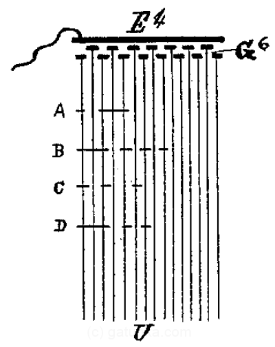
The reason why 15 wires were needed is because the longest letter at the time (the full stop, which in American Morse code is dot-dot-dash-dash-dot-dot) required 15 bits to encode (as 101011101110101). (In the later international Morse code, the longest was the 5 dash number zero, which would require 19 bits 1110111011101110111.) But this also reveals the weakness of Morse code for this system. For letters with short codes, a lot of transmission time is wasted sending nothing, and much of the gain of using multiplexing is thus lost. Clearly, Morse code is a bad match for this kind of multiplexing, and this was one of the forces that helped with the push towards fixed-length binary encodings such as the Baudot code.
Now, the receiving system is fairly simple. Let’s take a look at the apparatus again.
The cyan N block at the bottom is a selector which selects which of the 4 channels to receive. That signal is then sent to the printer, M, which prints out the Morse code as Morse code. (There was still no way to automatically convert Morse code into letter printing at the time, another problem which helped with the shift towards binary codes.)
Now, on to the motor. This one is kind of interesting because it is a cross between a steam-engine style reciprocating piston arrangement and a modern DC motor arrangement. Here is a top view.
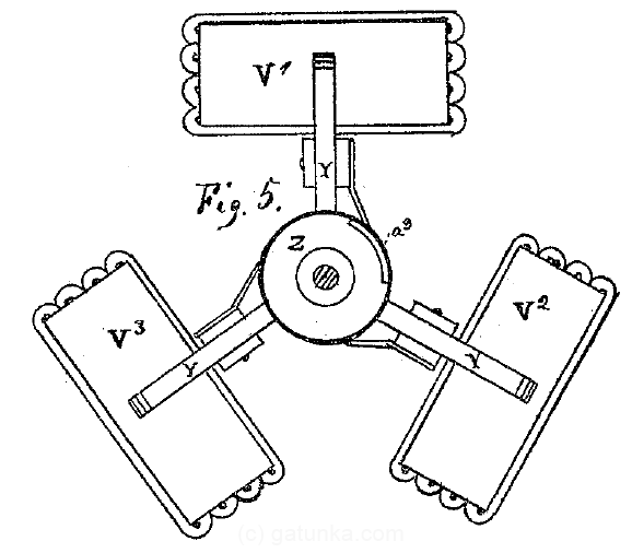
The 3 magnets are V1, V2, and V3. These pull down armatures, which are pivoted in the middle, and push up towards the wheel Z. This upward motion acts against a cam on the bottom of the wheel Z, thus mechanically creating rotational motion. The electromagnets engaged one at a time as the contact marked a3 came into contact with the corresponding brush. Here is a side view that might make things more clear.
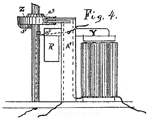
The cam is marked S and shown on the left side of the wheel. When the cam is above the armature at R, the magnet engages and pushes R into S. S is wedge-shaped, and causes the wheel to rotate. Obviously, this is a design that is not used anymore.
Related Posts
Tweet