Steam-Powered Letter-Printing Telegraph – US Patent 9505
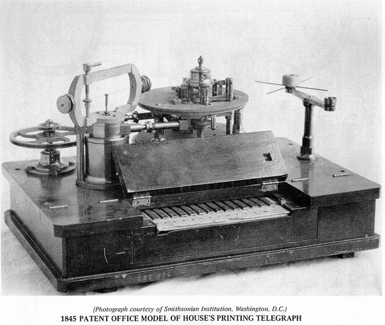
The letter-printing telegraph patented by Royal Earl House in the 1830s was one of the first devices to operate under virtually the same principles as modern computer terminals. They had a keyboard for typing in letters, which were then transmitted down a wire. They also had a printer for printing out the signal they received from the wire as letters on paper. (So theoretically, you should be able to hook one of these up to a modern Linux box as a /dev/tty device.) However, electronics in the 1800s were not particularly advanced, and it turns out that the biggest improvements that could be made to the device was the addition of steam-power. Here is a picture of the steam-assisted device from 1852 (from nadcomm.com. To get an idea of the size, the keyboard is basically a re-purposed piano keyboard):
For comparison, here is the steampunk keyboard of today that this kind of device inspired:

This article runs through the patent from 1852 and shows how steam was incorporated into the instrument to give a steam/electromagnetic/mechanical hybrid device, the kind of thing that steampunk idealizes. However, spoiler alert to all the steampunks out there, although the device was originally designed to run off steam, the inventor soon realized that compressed air worked much better, and the device was actually used as a pneumatic device in practice.
First, let’s take a look at a schematic of the entire thing (from the patent):
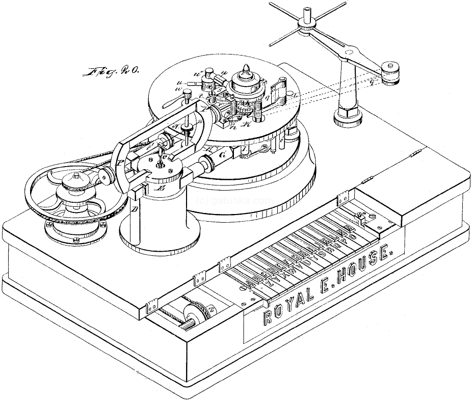
This device is composed of a transmitter unit and a receiver unit, the same as the earlier model. The transmitter is basically the same (although the keys are arranged in two rows, more like piano keys), so you can look at the earlier patent if you are interested. Where things get interesting is the receiver. Let’s start by highlighting the first stage of the receiver input.

Orange shows the steam/compressed air pipes, and green shows the electromagnetic actuator part that converts the incoming electrical signal into steam energy. Here is a side-on view (with a plan view inset).
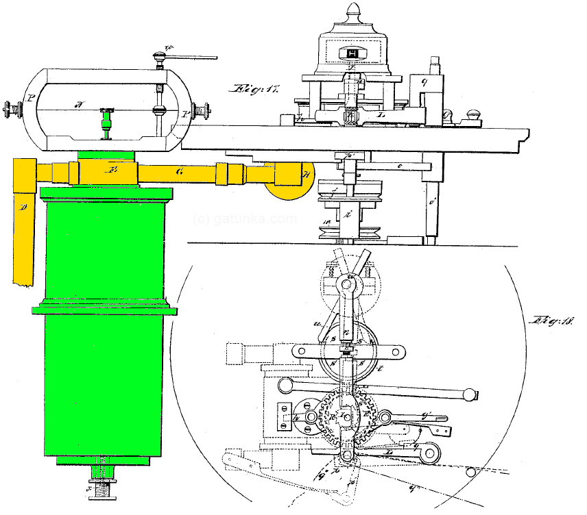
One of the key parts of the patent is the new arrangement of electromagnets in the actuator, which the inventor calls the “combination electro-magnet”. This new magnet was necessary to get enough force to actuate the valve, which had not been possible with previous electromagnets. As this side view shows, this magnet was the largest part of the device, with most of it hidden from view like an iceberg lurking beneath the surface. The bulk of the space is taken up by the wire winding of the electromagnet. Inside this was an actuator, which is arranged as follows.
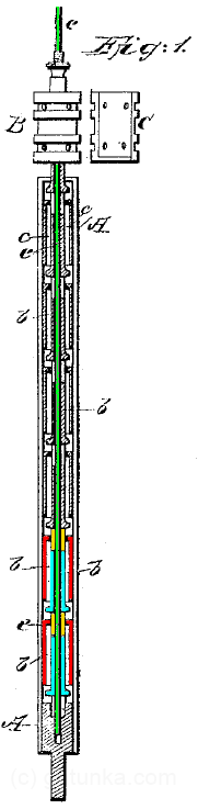
Inside the large non-magnetic cylinder at the bottom are a series of magnets that are fixed in place (shown red). Within these sits the rod (green), which is a non-magnetic metal. Another series of magnets (blue) and washers (yellow) are attached to the rod. This entire cylinder then sits in the middle of a big electromagnet (the big green thing in the earlier diagrams). Normally, the rod is in the lowered position. When the magnet is energized, however, it pushes up forcefully. (Or as the patent says “and hence, by this combination of magnet, of which I claim to be the first inventor and discoverer, I secure a great advantage in the acquisition of power.”)
At the top of the rod is what the inventor calls a “circular balance valve”. This is the part that fits into the steam/pneumatic piping. The following shows a plan section view (marked Fig. 2) of the steam pipes.
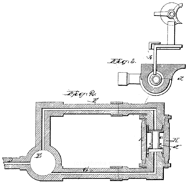
The steam enters from the left side (marked D, although this is hard to see) from any source of pressurized steam. The big area marked E is the valve chamber where the valve is seated. As the electromagnet is energized and de-energized, the valve moves up and down, alternately feeding the steam to pipe F or pipe G and turning the other pipe into an exhaust vent. This thus pushes the piston marked d back and forth in the piston chamber H, which drives an escapement backwards and forwards. The action of the escapement is then the same as the previous design (although arranged quite differently).
The rest of the design is mechanical again. Although the arrangement is quite different from the previous model, it achieves basically the same thing. Here are the details of the other parts. Note that mechanical power is provided by pulley and pause detection is achieved using a friction wheel. I can go into more detail if anymore is interested, but for now here are the remaining parts. Note that there are basically three vertical shafts. I’ll show them in order from front to back.
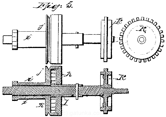
This is the type-wheel (which contained the type used for printing). The steam-driven escapement acted on this shaft. Rotational motion is provided via a string around the pulley part.
This next shaft along is used for pause detection. The top part which has the protruding catch is mounted on the shaft by friction. The shaft itself continuously rotates. The catch on the top, however, keeps getting pushed back by the rotation of the type-wheel. When the type-wheel stops (because the transmitter wants to print a letter), the catch is able to rotate freely, which activates the printing mechanism. The raised edge marked s and t is the part that frees the printing mechanisms and ensures only a single printing action until the pause finishes.
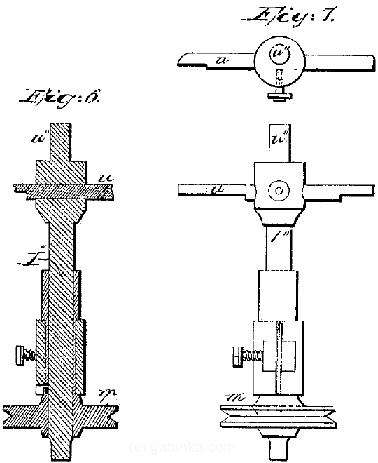
The back-most of the three shafts has a lever arm u which is normally caught against the raised edge (part s) of the previous shaft. When printing is actuated, it is freed from the part s, but catches against the opposite lip t, and thus only rotates through approx 30 degrees. This is enough to activate the printing mechanism. Again, the pulley for receiving the drive string can be seen at the bottom of the shaft.
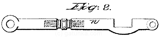
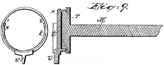
This shaft communicated the printing actuation from the back of the device to the printer at the front. The only notable point is the degree of adjustability, much more than the previous model, allowing the device to be fine-tuned.
Although the steam/compressed air only played a small role in the mechanism, it was an important one for obtaining sufficient power to drive the device reliably. Probably not quite as steam-y as the steampunk ideal, but at least it was a real device that was used in real life. There are also some posters of much later models available online:
Related Posts


- Details of an 1873 parent for synchronous multiplexing of Morse Code which demonstrates why binary codes are needed
- Details of a patent by Thomas Edison from 1876 which uses tuning forks to multiplex telegraphy signals
- Details of Baudot’s original patent from 1882 which uses electromechanical computing principles to decode 5-bit serial communication
- A history of encodings up to ASCII with links to the mechanical systems used to handle the encodings
- Japanese Typewriters: How a typewriter with thousands of characters works
- Why Japan Didn’t Create the iPod: How the complexities of the Japanese language affected the Japanese digital culture
Tweet