Baudot Code Telegraph – US Patent 388244
This device is somewhat of a revolution in telegraph technology from the 1870s. It uses a fixed-length 5-bit binary encoding, the kind of encoding that we would expect to see in silicon-based electronics equipment. Baudot created a receiver that resembles a mechanical computer to perform the decoding and printing. Looked at in modern terms, it uses a 5-bit latching transfer register and a second 5-bit decode register for actually printing the received codes as human readable characters instead of squiggles or dots on paper. The encoding used by the device is named after its inventor Emile Baudot. I’ll run through the entire device, although it is the receiver where things get interesting.
The device is inherently capable of multiplexing, but the original form shown in the patent is only a simplex device. The code is sent down the line in serial format, which is achieved using a rotating distributor. Multiplexing could thus be trivially achieved by adding segments to the distributor. Baudot originally used a keyboard connected directly to the distributor for transmission, meaning that the keyboard operator had to type in sync with the rotation of the distributor. The keyboard had 5 keys, meaning that the operator had to learn the binary codes for each letter, but this was later replaced by a punched paper tape system, which made the whole thing a lot easier to use. Here is a schematic that shows conceptually how the distributors performs serializing/deserializing.
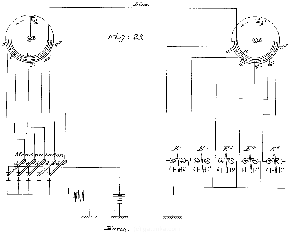
In this figure, the side on the left shows the keys at the transmitter, and the side on the right shows the receiver which activates the receiving electromagnets E1 to E5. The reason why only half of the distributors are used is that the other half was used for synchronization, as will be described later. Now, the actual arrangement used in the device is slightly more complex than the above conceptual drawing. Here is the schematic of the actual device.
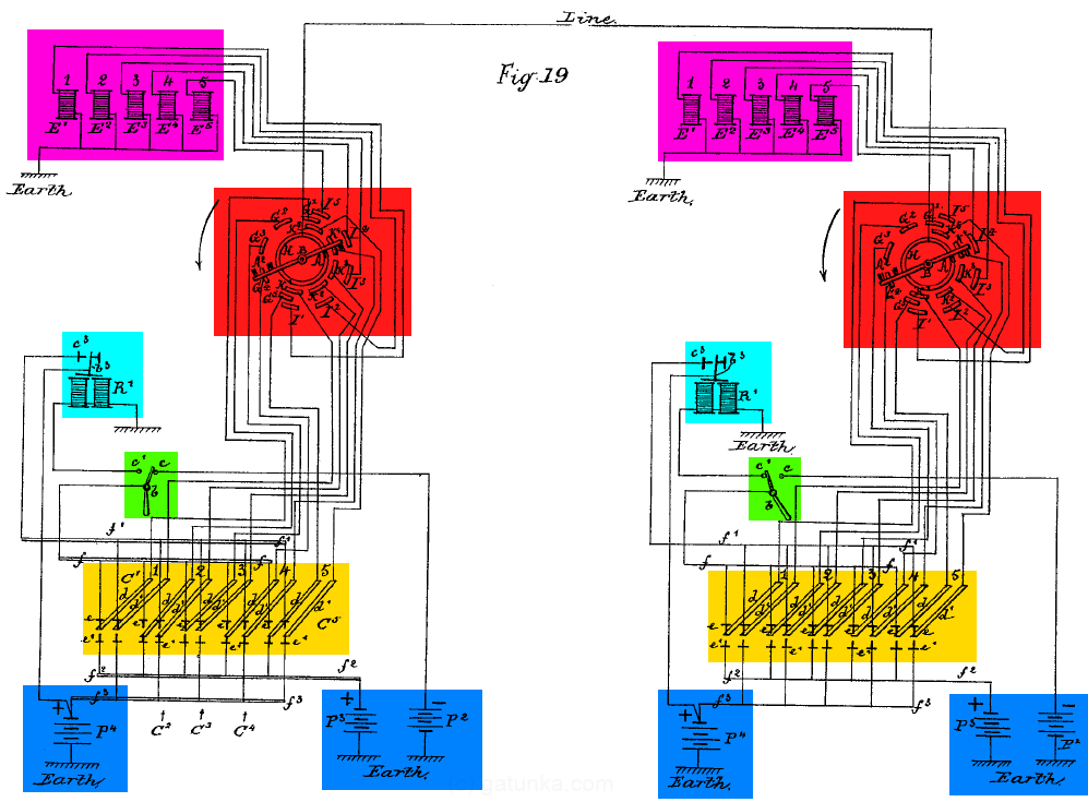
The first thing to note is that we have switches for choosing receiver/transmitter (highlighted in green). In this case, the station on the left is the transmitter and the station on the right is the receiver. Now let’s follow the power through the system from the left hand side transmitter. There are three batteries at the bottom (blue). The battery P4 powers the local apparatus, while the batteries P2 and P3 used for transmitting positive and negative signals down the line. (The transmission line signaling was +/-). The keyboard (orange) has five keys, each of which activates two different circuits. The left side of each key sends a polarized signal (positive for logical 1 and negative for logical 0) from the P2 and P3 batteries through the red distributor onto the telegraph wire. The right side connects the local battery P4 through the same distributor and to the local printer (represented by the electromagnets E1 to E5 in the purple area). The signaling here is positive for logical 1 and not connected (or high Z) for logical 0. This produces a local copy of the transmission.
At the receiver, the line runs through the red distributor to a polarized relay (cyan). This accomplishes two things. First, it converts the polarized signal (+/-) from the line back into the signal (+/high Z) used by the printer. Second, it acts as an amplifier, taking the weak signal from the telegraph line and relaying it into a strong signal using the P4 local battery. This then runs back through the distributor and into the purple magnets E1 to E5 which drive the printer.
Here I just want to discuss the line signaling for a minute. The signaling that is used in earlier Morse code style telegraph (positive voltage = logical 1, not connected = logical 0) is not particularly suited to the asynchronous multiplexing schemes that were first attempted in conjunction with Morse code. The reason is that there is no distinction between logical 0 (not connected) and the timing window when other virtual circuits are connected to the main line (again, not connected). A simple way to overcome this, however, is to use polarized signaling (positive voltage = 1, negative voltage = 0, and not connected = ignore) combined with a flip-flop – which in modern electronics is a type of circuit that can be switched between two logical values, but retains its value when not being switched. This is relatively easy to implement using electromechanical devices by using an electromagnet with a polarized armature without any springs that flips and flops between two stable positions. (Note: I have no idea if this was the basis for the name “flip-flop”, but it certainly fits.)
The point is that the entire input side of Baudot’s apparatus is remarkably similar to this kind of arrangement, consisting of polarized communication via a polarized flip-flopping relay. However, the device in this patent uses a synchronous multiplexing arrangement which renders all of this unnecessary, and the polarized relay in the device contains a spring such that it no longer acts as a flip-flop.
Next, let’s look at the distributor in more detail.
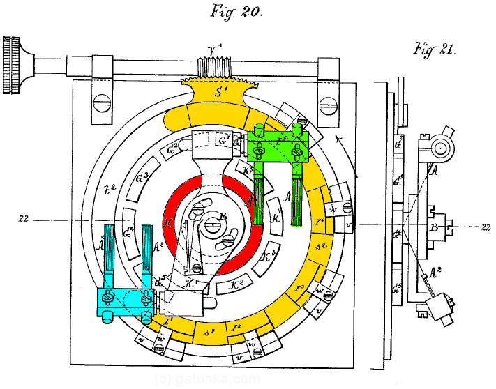
As you can see, the rotating arm has two sets of brushes. The first set (green) connect the main line contact H with the 5 bits of the polarized signal, labeled G1 to G5. On the receiver, these run off to the polarized relay and return a non-polarized signal to the contacts K1 to K5. The second brush (cyan) then connects these non-polarized signals with the contacts I1 to I5 that run to the electromagnets in the orange part of the disk. The knob at the top can be turned to move only the orange part of the arrangement, which is used for fine-tuning the timing. The pieces marked v outside of the orange circle are the conductors that run to the printer.
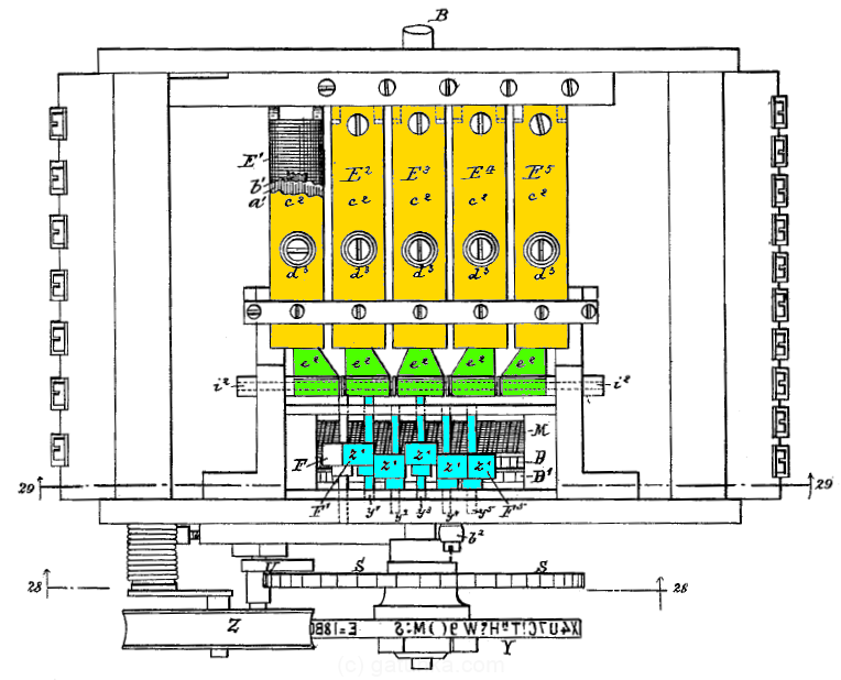
Next we have the printer. Here is a side view of it.
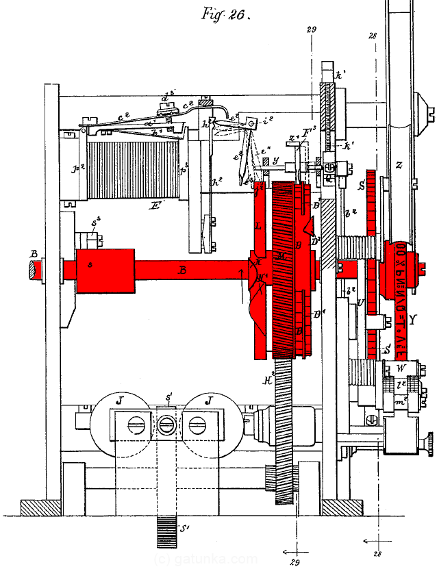
First, notice the shaft marked B which runs through the center of the apparatus. This is the main timing wheel. Everything colored red sits on this shaft and rotates together. The shaft is also connected directly to the distributor arm (which would be on the left of the diagram). The direction of rotation is indicated by the arrow. Now, let’s focus first on the transfer and decode registers. This cross-section view shows 1 bit out of the 5 bits that make up the registers. Here I’ve color-coded the separate stages of the device:
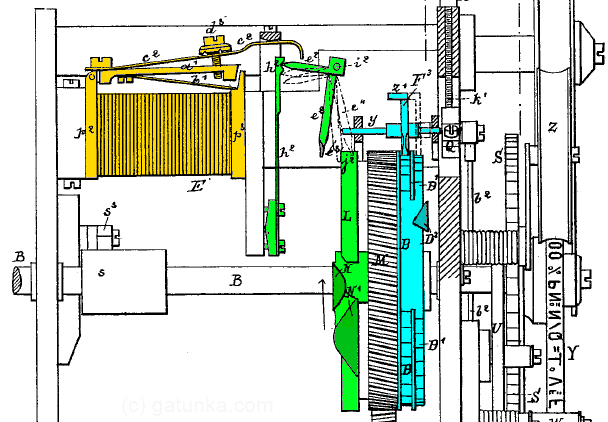
On the left (orange) we have the electromagnet which is driven from the distributor. In the middle (green) we have the latching transfer register, and on the right (cyan), we have the decode register. Now, focusing on the transfer register, let’s have a look at the logical 0 and logical 1 positions.
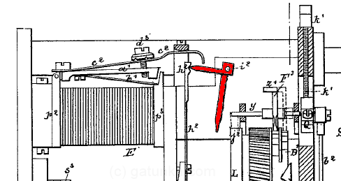
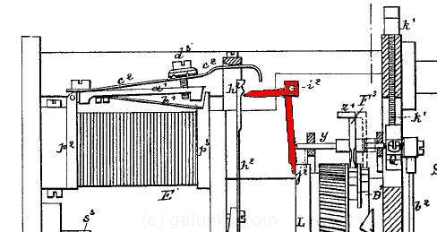
What we have here is an analog version of a latch, one which actually uses a latch. The bits start in the logical 0 position, and are held there by the spring latch, h2. The input from the electromagnet knocks the bit out of the spring latch and into the logical 1 position, where it remains. The unit also has an output and a reset function. Looking back at the full stage, notice the curved cams in the wheel (shaded a darker shade of green).
Once per revolution of the master timing shaft B, the first cam catches the lever only if it is a 1 bit. The lever is pushed to the right, which is the output function that transfers the latched value into the decode register to the right. The next cam is the reset cam, which pushes the lever back up into the logical 0 position where it is again retained by the spring marked h2.
Looking at the decode register, we again have two bit positions as follows:
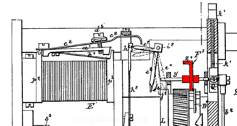

This time, notice how the bottoms of the register pin fits into one of two grooves on a flanged wheel. This wheel is the decoder wheel, which we’ll cover later, and the flange in the middle between the bit positions locks the value of the bit. There is a break in the flange at which point we have a reset cam (the darker blue triangle) which resets the pins back to logical 0. The flange remains broken after this, and is aligned with the transfer cam from the transfer registers. Once the value has been transferred from the transfer register, the flange begins again, locking the values in place.
Now, I’ve got to say that I love this because it means that this device effectively ran in pipelined operation, much like modern CPUs. In this 2-stage pipeline, the first stage gets a full clock cycle to de-serialize the input from the line, and the second stage gets a full clock cycle to perform decoding and printing.
This description has only shown the operation of a single bit, so here is a view from the top which shows how all five bits were arranged with the three stages colored as before.
Decoding
The next trick is decoding the input 5-bit values into actual letters. In the modern world, we could probably treat the codes as binary numbers with values of 0 to 31 and use table lookups or the like. However, in the age before computers there was no reason to treat the codes as numbers at all. They were simply a sequence of 5 values which formed a code. (Although it didn’t take long for someone to realize the usefulness of treating the code as binary numbers.) Decoding is thus achieved by comparing the decode register against every possible combination until a match is found. The mechanism for achieving this sounds like something out of a tech-company interview, but was quite ingenious for the time. Put as a tech question, what is the smallest binary string that contains all possible 5-bit binary numbers as sub-strings? Here is the circumference of Baudot’s decoder ring which contains the answer:
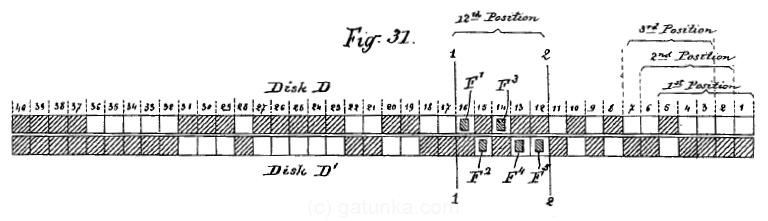
The top row corresponds to bit 0 of the decode register, and has gaps (white squares) that correspond to 0 bits. The bottom row corresponds to bit 1 and has gaps that correspond to 1 bits. In answer to the above question, we need 36 bits for the decoder string. The 37th position onwards has no gaps, meaning that it will not match either 1 or 0 bits. To see how it worked, let’s take a look at the view from the back.

From this view, the decoder wheel rotates clockwise. The five cyan levers are the pins of the decode register. The purple lever to the left is attached to a spring (not shown here) such that it pushes the tops of the 5 register pins towards the right. This pushes the fingers underneath onto the decoder wheel. Once the fingers line up with holes in the decoder disc, the levers all tilt to the right and activate the printing mechanism. Note that there is no need for the rotation to stop during the printing. The printing occurs in one continuous action. I’ll get into the printing mechanism later, but I just wanted to comment on the analogy of the mechanism up to now to a computer.
Let’s call the transfer register TX, the decode register DX, and use the pneumonics CLR (clear), OR (logical or), and CAP (compare and print) for the operation of the decoder wheel. The rotation of the wheel thus continuously runs the program:
CLR DX
OR TX,DX
CLR TX
CAP #16
CAP #8
CAP #4
CAP #18
CAP #9
CAP #20
CAP #10
CAP #21
CAP #26
CAP #13
CAP #22
CAP #11
CAP #5
CAP #2
CAP #17
CAP #24
CAP #12
CAP #6
CAP #19
CAP #25
CAP #28
CAP #30
CAP #31
CAP #15
CAP #23
CAP #27
CAP #29
CAP #14
CAP #7
CAP #3
CAP #1
CAP #0
It’s a long way from being a Turing machine, but it is still an interesting approach to digital communication. Now, on to the printing mechanism. Here’s the same view as above, but with more components added.
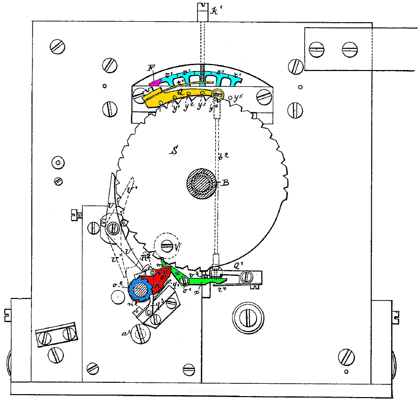
The orange component at the top is attached to the purple lever from the previous diagram. When we get a code match, it rotates to the right, pushing the push rod down onto the green lever at the bottom. The left arm of this green lever has a catch that holds the red arm in place. When this is released, the spring on the right side throws the arm into the notch in the big rotating wheel. This drives the red arm, which performs the printing (which happens in the next layer up) by swinging the paper against the wheel. The blue ratchet is used to advance the paper. The cam marked V on the big wheel then resets everything at the end of the cycle.
Adding on another layer of components, we can see the full paper path and the type wheel.
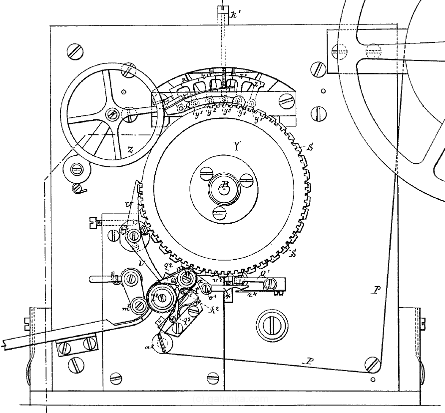
This original model does not use any shift states. However, soon after Baudot began using his device, he added the first shift codes to it. Instead of having a single type wheel, he switched to having two type wheels in parallel, and two of the character codes were decoded not as printable characters, but as command codes that actually shifted the printing mechanism between the 2 parallel type wheels. This gives a total of 60 printable characters. As a challenge, you might try to imagine how these shift codes could be incorporated into the mechanical design.
Related Posts
- Japanese Typewriters: Mechanical typewriters capable of typing thousands of different characters
- Unicode and ASCII, UNIX and Windows, and Character Codings
- Steam-powered telegraph from the 1850s
- A letter-printing telegraph from the 1830s. Input by keyboard and output to printer
- Why Japan Didn’t Create the iPod: How the complexities of the Japanese language affected the Japanese digital culture
Tweet