Letter Printing Telegraph – US Patent 4464 – Receiving Station
This is the receiving station for the letter-printing telegraph described here. This is a lot more complex than the transmitter, so we’ll break it into stages. This first stage is responsible for converting the electrical signal back into a mechanical signal. Here is the pic from the patent.
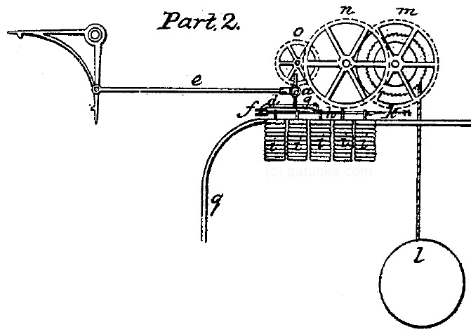
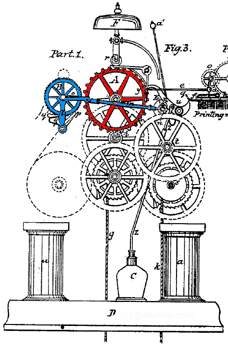
First stage of receiver, side view:
To make it easier to understand, I’ve colored in various parts:
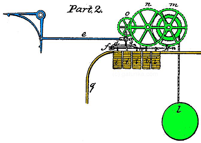
The electrical system is orange. The signal is input from the right hand side and runs through a set of electromagnets and then to ground. The mechanical input (green) is energy from a weight + ratchet combination, the same as the transmitter unit. This transmits clockwise rotational energy to the gear marked o. The mechanical output system is colored blue. The final output moves the shaft e left and right with each 0 and 1 input to the electrical system. The leftmost part is an escapement, which rotates around the axis. (Note that supporting structures are not shown, so you have to imagine that the axles are all held in place.) The key components here are at the point where the three systems meet.
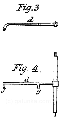

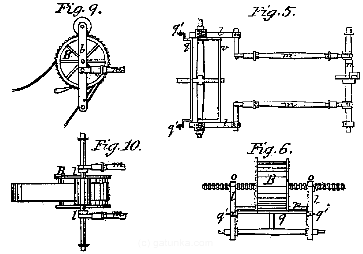
The shaft marked d sits just above the armature of the electromagnets, with pin J hooked into the armature. When the magnet is energized, it gets pulled down, pulling down the pin g with it, and when the magnetic is de-energized, it springs back up, as does the pin g. Above this sits the shaft marked Fig. 5. This shaft sits exactly at the point where the blue and green systems meet. The gear r is driven by the green mechanical input. There are two arms b and c of different lengths attached to this same shaft which spin with the shaft. When the d shaft is in the lowered position, the long arm c catches on the pin g, and when it is in the upper position, the long arm is released and the short arm b catches on the pin. Thus each activation or deactivation of the electromagnet allows the axle to rotate through 180 degrees. Next to the arms b and c is an eccentric wheel – a lop-sided wheel larger on one side than the other. With every 180 degree rotation, this then pushes the blue output shaft in and out. Thus the incoming electrical signal is converted into a mechanical signal.
Now, in case you are wondering why such a complicated mechanism is used when the same thing could be achieved using a solenoid, the reason is that the inventors didn’t know how to make a magnet powerful enough to be able to use directly, and so this kind of complex, indirect conversion mechanism was needed. Interestingly, although the knowledge to create more powerful magnets was known by the physicists of the time, it was not used by many of the inventors who instead stumbled on through trial and error.
Second Conversion Stage
Now let’s look at the rest of the receiving station. Note that the stage we have already looked at is in the middle marked “Part 2” in the patent.
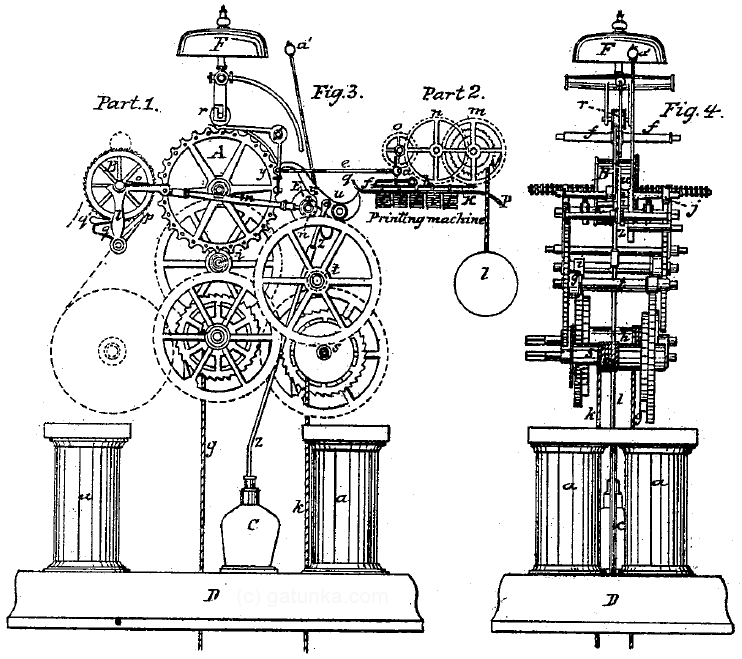
This probably looks complicated because it accomplishes a number of different things. However, it is not so hard if we look at individual parts. In the following diagram, we have the input from the first stage mechanism shaded blue, and we will first focus on describing the components shaded red.
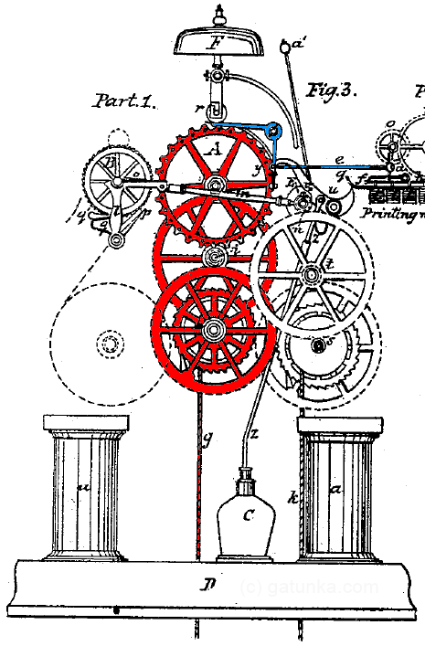
In the highlighted mechanism, we have another weight/ratchet/reducing gear combination. This mechanism is acting on the red wheel at the top, which is called the type wheel. The following shows this type wheel in detail. In terms of the scale, note that this wheel has a diameter of 6 inches.
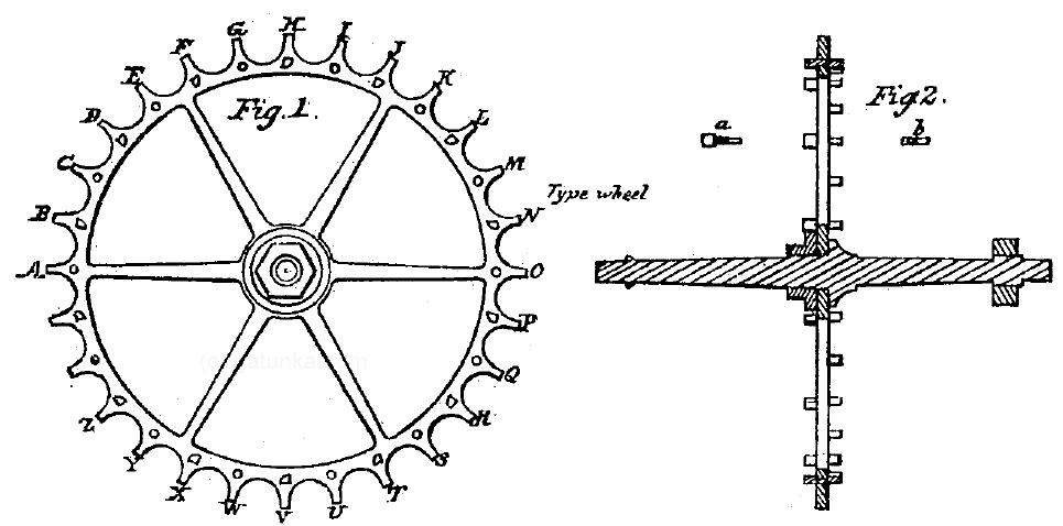
Now the type wheel has several functions, but at this stage we are only interested in the 14 pins which stick out from the back side of the wheel (the 28 pins which stick out from the front side are discussed below). These catch against the blue escapement from the previous stage, allowing the wheel to rotate by 1/28 of a turn with each change in input. The result is that this type wheel remains in perfect synchronization with the shaft under the keyboard at the transmitter, rotating and pausing exactly in sync with the transmitter.
At this point we have everything that is needed for what was called an “indicating telegraph”. If we simply stuck letters to the type wheel and placed a window at the appropriate location, an operator would see the letters flipping through until the sender pressed a key. This would stop the wheel, and the receiving operator could write down the letters where the wheel paused. For printing, though, we need more.
Detecting Pauses
The next stage is that the device needs to be able to detect pauses in rotation, and activate the printing mechanism when a pause occurs. The main components responsible for this are shown below.
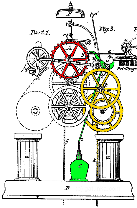
The red type wheel rotates counterclockwise in synch with the sending station. The green lever arm beside it is arranged so that it falls towards the left, into the path of the pins on the face of the type wheel. While the type wheel is spinning, the pins continually catch the falling lever and push it back up. When the spinning stops, however, the lever arm sinks down into the gap between pins. The bell shaped thing at the bottom of the green arrangement is a hydraulic regulator, which provides resistance that slows down the rate at which the lever descends while allowing the lever to move back up without any resistance. Details on the internals are available here..
Again, we have another weight/ratchet/downgearing combination (colored orange) which provides rotational power. At the top of this gear set is an eccentric wheel shown below.
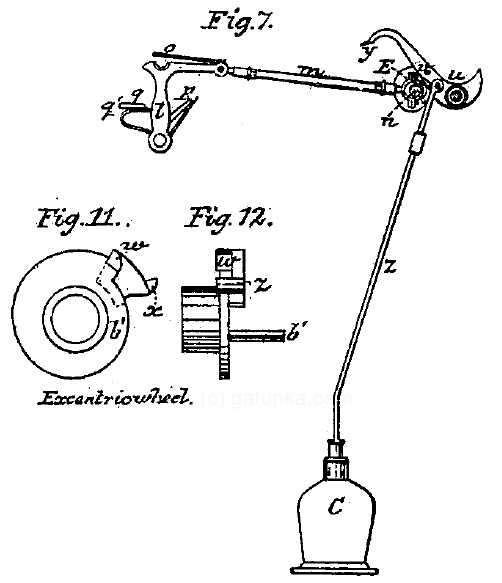
While the type wheel is spinning, a catch on the lever holds the eccentric in place and stops it from rotating. However, when the wheel stops and the lever descends, the eccentric is released and is allowed to make one revolution. At the end of the revolution a different part of the eccentric catches on the lever in the lowered position, preventing it from performing more than one revolution. The eccentric has two purposes. One is to ring the bell at the top of the receiver (to notify the operator of an incoming transmission), and the other is to activate the printing mechanism.
Here, the blue part represents the printing mechanism. The type wheel which we discussed earlier has type corresponding to each of the letters formed on the tips of the wheel. Once the eccentric is activated, it pushes the blue printing mechanism slowly out to the left, and then suddenly releases it, dropping it and the paper onto the type wheel and printing the letter. Paper is fed up from a role underneath, and a series of ratchets and springs advances the paper. The details are shown below.
And that cover everything.
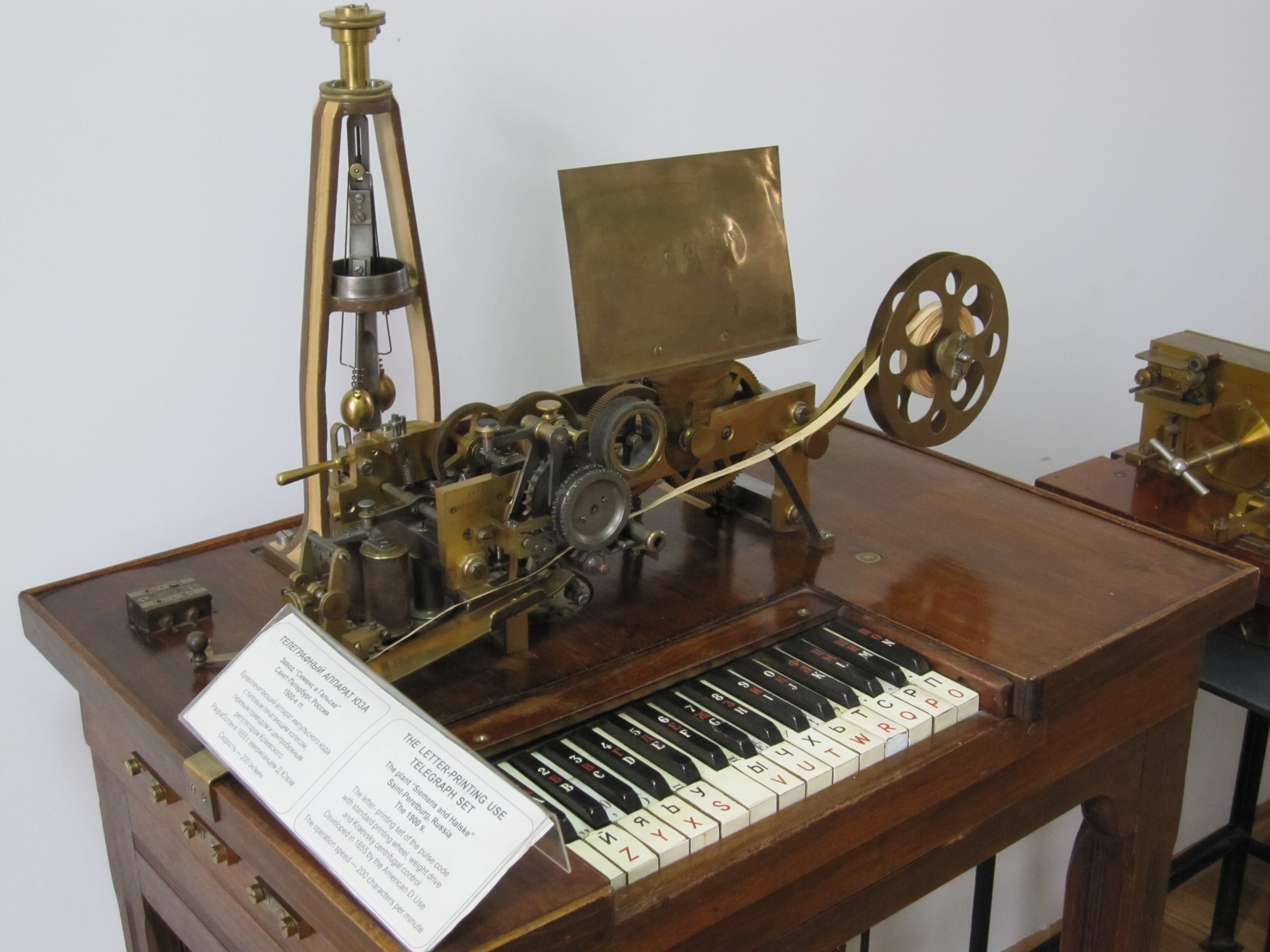
Unfortunately, I was not able to find a picture of an actual device. However, if you want to get an idea of the size of these things, there is a picture from Wikipedia which shows a similar device from 60 years later which consists of basically the same components. Hopefully this will give you an idea of the scale and complexity of these devices compared with the minimalist Morse code key/buzzer type of telegraph.
Now for any steampunks out there who are disappointed that there was no steam involved in this device, the same inventor followed up with a steam-powered version in 1952, which I have detailed here because it is quite interesting.
Related Posts
Tweet